
Author: David Bussé, MD, MBA (EM Resident Physician, UTSW / Parkland Memorial Hospital) // Edited by: Jamie Santistevan, MD (@jamie_rae_EMdoc – EM Physician, Presbyterian Hospital, Albuquerque, NM); Manpreet Singh, MD (@MPrizzleER – Assistant Professor of Emergency Medicine / Department of Emergency Medicine – Harbor-UCLA Medical Center); and Brit Long, MD (@long_brit – EM Attending Physician, San Antonio, TX)
Welcome to this edition of ECG Pointers, an emDOCs series designed to give you high yield tips about ECGs to keep your interpretation skills sharp. For a deeper dive on ECGs, we will include links to other great ECG FOAMed!
The Case:
A 76-year-old male with HTN, DM, CAD, and 3rd degree heart block status post pacemaker placement 8 years ago presents to your ED with dyspnea on exertion and an episode of syncope earlier today. His triage vitals are T 37.2C, HR 38, BP 118/78, RR 18, and O2 Sat 96% on room air. The patient you see before you is well-appearing and answering questions appropriately. He is able to state that, due to insurance issues, he has been unable to arrange an appointment with a cardiologist for the last 3 years.
His initial ECG reveals the following:

Pacemaker Function

Pacemakers are comprised of multiple components:
- The pulse generator contains the battery. It is implanted in the soft tissues or muscles of the anterior chest wall. Most pacemakers have a battery life of 5-10 years [1]. Battery life depends on how frequently the pacemaker senses and paces, making accurate prediction of its duration difficult. Timely replacement requires appropriate follow-up.
- Pacemaker leads connect the pulse generator to the myocardium. Leads are placed in the right ventricle for single chamber pacemakers. Dual-chamber pacemakers have leads in the right atrium and right ventricle. Lastly, biventricular (resynchronization) pacemakers place leads in the right atrium, right ventricle, and coronary sinus (which paces the left ventricle). Fracture of the leads or breakdown of the insulated coating may lead to improper pacing/sensing functionality.
- Pacing occurs when a potential difference (voltage) is applied between two electrodes. The stimulation threshold is the minimum amount of energy required to depolarize myocardium, described by amplitude (volts) and duration. These features are programmable and affect battery longevity [8].

Pacemakers are fully described by a 5-position code, with the first 3 positions defining the function of the device [1, 2, 7]. These can be remembered by the mnemonic PaSeR1 – pacing function, sensing position, and response to sensing.
The most common setting for dual-chamber devices is DDD [1], wherein the pacemaker paces and senses both the atrium and the ventricle. If a native beat is sensed, the pacemaker is inhibited. If no native beat is sensed after a set time interval, the pacemaker delivers a triggered beat.

This is a patient with a normally-functioning DDD pacemaker:
Pacemaker Malfunction
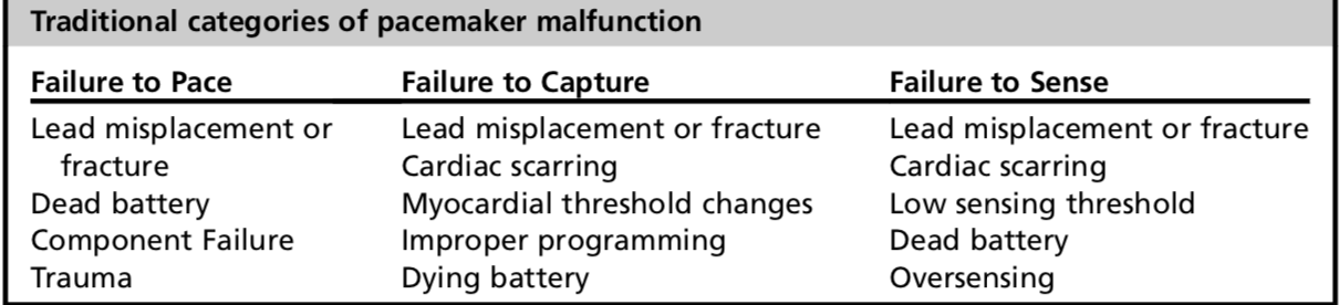
Pacemaker failure has traditionally been divided into 3 categories:
- Failure to pace suggests that the pulse generator is not providing sufficient voltage output to depolarize myocardium. The ECG shows neither pacer spikes or pacer-induced QRS complexes, but rather the native rhythm of the patient.
- Failure to capture occurs when a pacemaker pulse is given, but the impulse is unable to depolarize non-refractory myocardial tissue. Pacer spikes are seen on an ECG, but there is no cardiac response. Once again, the patient’s native rhythm is seen on the ECG. Fibrosis from the local inflammatory response weeks after implantation (decreased incidence due to steroid-eluting leads [8]) in addition to lead fracture/dislodgment, twiddler’s syndrome, and cardiac perforation may be the culprits [7].
- Failure to sense includes both oversensing and undersensing. With oversensing, the pacemaker misinterprets other signals (peaked T-waves, electromagnetic interference, skeletal muscle activity) to be QRS complexes, inhibiting response and failing to initiate pacing [1, 7]. With undersensing, the pacemaker is unable to correctly interpret native cardiac activity due to changes to intracardiac signals (myocardial ischemia, new bundle-branch blocks, PVCs [1, 7]). Sensitivity can be reprogrammed to improve these issues [8].
- This historical categorization has little value in the acute setting, as its causes tend to overlap greatly, and all of them are managed similarly.
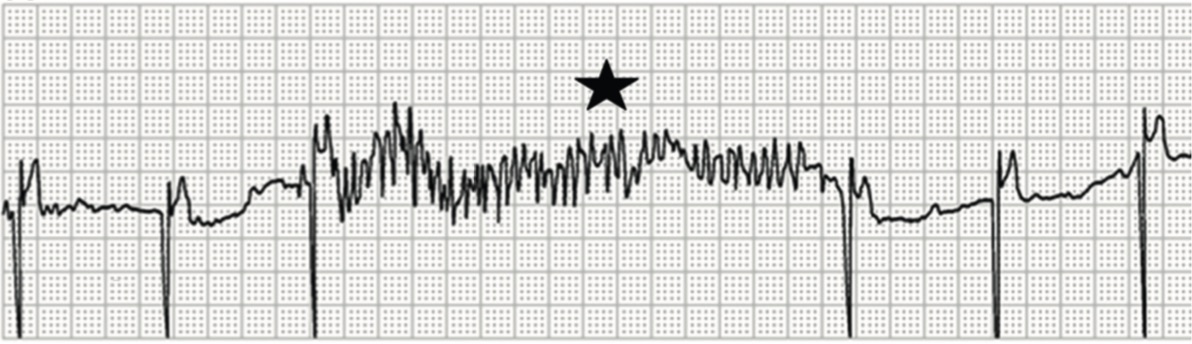
Myopotential oversensing and inhibition of pacing: Skeletal muscle activity is confused for cardiac activity (star) resulting in inhibition of pacing in a patient with a pacemaker programmed to VVI mode.

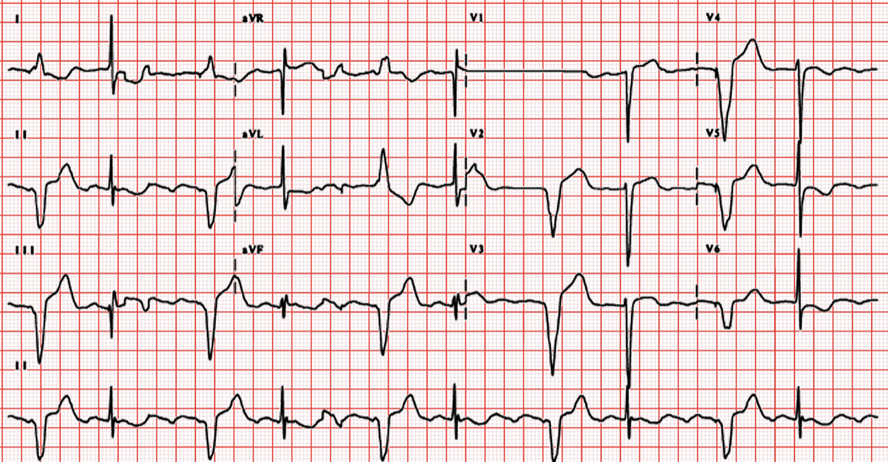
Undersensing and loss of capture: The P-waves are marked with asterisks. Undersensing (arrowhead) is noted when a P-wave is shortly followed by a pacing spike. Loss of capture (arrow) is noted when an appropriately timed pacing spike fails to generate a P-wave.
ED Approach to Pacemaker Malfunction
- Suspect pacemaker malfunction with complaints of lightheadedness, fatigue, palpitations, hiccups, confusion, dyspnea, muscle twitches, and syncope.
- The history should elicit whether the patient has any underlying problems leading to pacemaker malfunction. These include ACS, trauma, medication changes, or recent device reprogramming [1, 2].
- Patients are given cards with the device’s type, model, manufacturer, and the date the device was implanted.
- Ask patients to provide their pacemaker card.
- The physical exam should begin with a review of vital signs, mental status, and cardiopulmonary status. Note signs of infection, migration, or trauma at the implant site [2, 7]. Also look for JVD, cannon A waves, pectoral muscle twitching, and new cardiac murmurs/rubs.
- Obtain an ECG to determine whether an unstable bradycardia is present. Compare it to prior ECGs, looking particularly at axis changes [2].
- The ECG of a single ventricle-paced patient will show ventricular pacer spikes and a LBBB with left axis deviation due to the placement of the electrode in the RV [7].
- Biventriculrar pacers capturing the LV free wall demonstrate a dominant R wave in V1 and a QS complex in lead I, indicating a wavefront propagating away from the LV6.
- ST segments and T-waves should be discordant with the QRS.
- Obtain PA and lateral chest radiographs to check for lead dislodgement, fracture, or pneumothorax. Should a patient be unable to produce the pacer card, an overpenetrated chest radiograph can be used to determine the device maker by identifying the company symbol [1, 7].
- Obtain serum measurements of electrolytes and any cardiotoxic drugs in addition to cardiac biomarkers in the appropriate setting. Metabolic derangements including hypothyroidism, acidosis, and hypokalemia can alter the threshold potential required for pacing [2].
- Management is dictated by the patient’s symptoms and hemodynamic status. Transcutaneous pacing pads should be placed on the patient in an anterior-posterior configuration whenever malfunction is suspected [1, 2, 7]. Apply standard ACLS protocols should a patient be bradycardic with symptoms of hypoperfusion.
- When hemodynamically stable, interrogate the pacemaker. Interrogation yields information on battery life, sensing and pacing thresholds (under/oversensing), integrity of the lead system (lead fracture), and recordings of cardiac rhythm [1, 6, 7]. Interrogation can indicate proper functioning or presence of arrhythmias that help risk stratify the patient.
- Interrogation involves radiofrequency communication with the pacemaker by placing a wand over the device. The wand is attached to a programmer that performs the interrogation, and is specific to each device company.
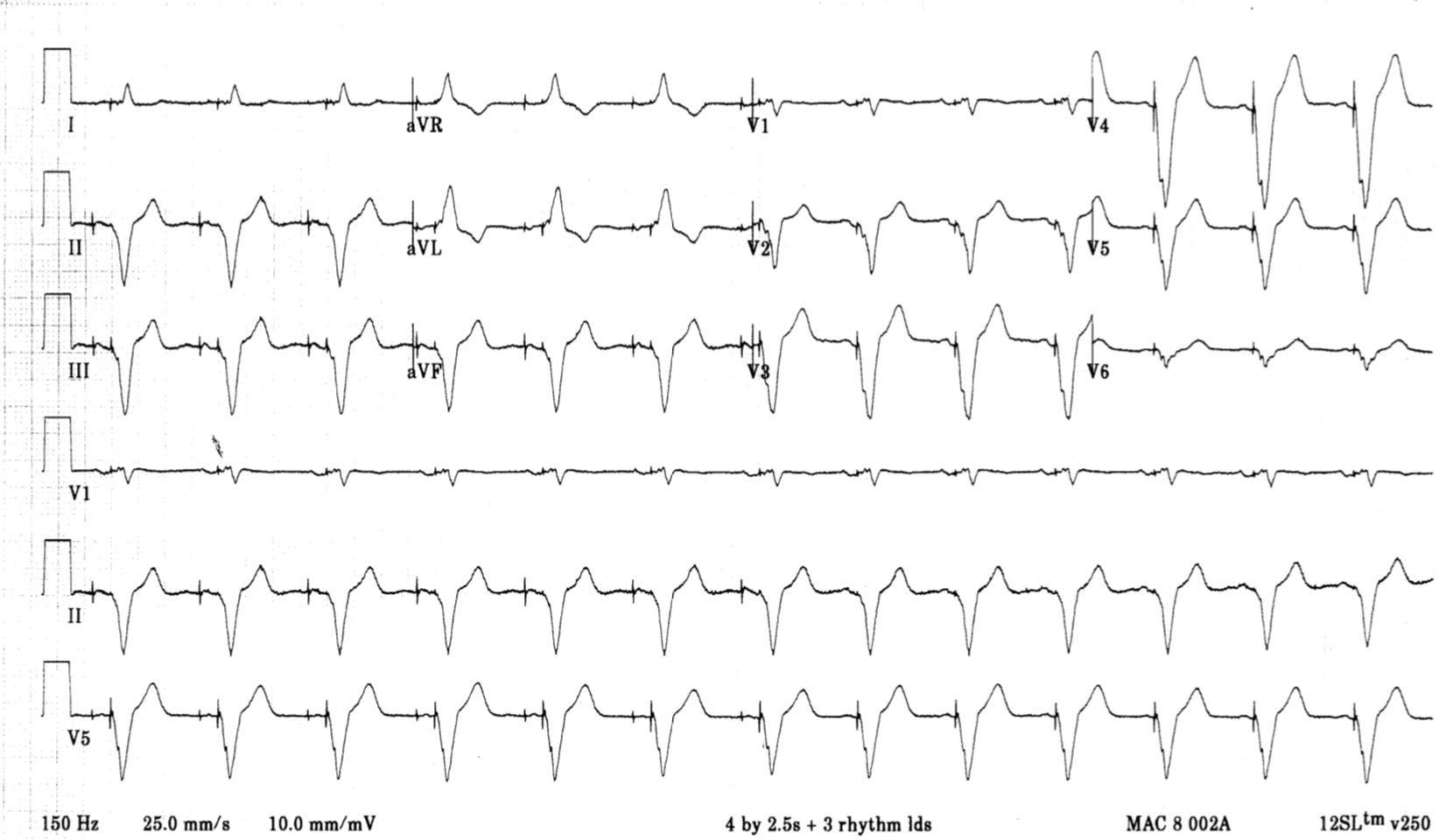
This is an example of a patient with bradycardia despite pacemaker placement:
Pacemaker-induced Dysrhythmias/Syndromes:
- Apply Sgarbossa criteria to patients with pacemakers when ACS is suspected.
- Pacemaker-mediated tachycardia (PMT) is a reentrant loop tachycardia unique to dual-chamber pacemakers [7]. A PVC is delivered to the atria in retrograde fashion. This ventricular depolarization stimulates atrial sensing, triggering another ventricular depolarization; a loop is created setting the dysrhythmia at the upper rate limit of the pacemaker. A clinical magnet or any therapy that increases the refractory period at the AV node (adenosine, CCBs, BBs) will terminate the arrhythmia [1].

Pacemaker mediated tachycardia: The first beat illustrates AV sequential pacing, followed b a PVC beat. The PVC starts a new VA interval. Any AV decoupling event (most frequently PVCs) can retrogradely conduct to the atrium. An atrial event is sensed if it falls outside of the post-ventricular atrial refractory period (PVARP). The VA interval expires, and a new AV interval is triggered. Ventricular pacing occurs at the end of the AV interval setting up a circuitous series of events termed pacemaker-mediated tachycardia.
- “Upper rate behavior” may induce 2:1 block [8]. In dual-chamber pacing mode, the device paces in a 1:1 (A:V) fashion until reaching the programmed upper ventricular rate. As the atrial rate increases, ventricular pacing cannot violate the upper rate limit, resulting in progressively longer AV intervals. As the AV interval lengthens, abrupt 2:1 block may develop with a sudden slowing of the ventricular rate (the ventricular rate becomes half of the maximum tracking rate), inducing symptoms [8].
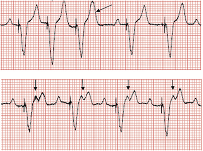
Upper rate behavior in a dual chamber pacemaker: With an increase in sinus rate above 130 bpm, some of the P-waves fall in the PVARP period (arrows) and are not tracked. Progressive PR prolongation is seen before blocked beats (pacemaker Wenckebach). When the sinus rate reaches the TARP (AV interval + PVARP), every other P-wave falls in the PVARP and is not tracked, resulting in an effective ventricular rate of 75 bpm, and an abrupt drop in heart rate (2:1 block rate in this patient). These are not retrograde p waves.
- A “runaway pacemaker” involves dysfunction of the pacemaker generator [1, 7]. The paced rate is greater than the programmed upper limit (up to 400 bpm). Use clinical magnets to abort the arrhythmia. The last resort is to disconnect the leads from the pulse generator (cutting open the pocket).
- Twiddler’s syndrome occurs when patients disturb/dislodge leads by manipulating the generator [7]. A CXR will show the twisting of leads about the generator. Surgical correction is necessary.

Check out this post on Learning Radiology: http://learningradiology.com/archives05/COW%20141-Twiddlers%20Syndrome/twiddlerscorrect.htm
- Pacemaker syndrome describes abnormal patient symptoms (dyspnea, dizziness, chest pain, palpitations) after ruling out all other causes of pacemaker malfunction. Common to single chamber pacemakers, it is thought to be due to an abnormal depolarizing relationship between the atria and ventricles, or AV dyssynchrony [1]. Correct by optimizing pacing modes/programming.
- The use of MRI in patients with pacemakers is contraindicated given the risk of triggering high-rate pacing [7]. CMR conditional pacemakers are specifically designed to be safe in an MR environment, but these account for the vast minority of devices. CMR-conditional devices have minimal ferromagnetic material, altered filtering, and redesigned lead conductors to minimize current induction and heating of tissue [8].
Additional Considerations:
- Patients may present to the ED soon after pacemaker placement with pain and swelling at the pocket site.
- Bleeding into the pocket is a common complication, and may dissect fascial planes [7, 8]. Large hematomas require surgical evacuation. Do not aspirate!
- Erythema, edema, fluctuance, and dehiscence of the incision site are suggestive of infection. Most infections are caused by S. aures and S. epidermidis, so empiric coverage with vancomycin should be initiated in the ED [1, 2, 7].
- Infections that arise later tend to affect pacemaker leads [2, 8]. Suspect bacteremia, lead vegetations, and septic pulmonary emboli. Confirm the diagnosis with blood cultures and TEE. Vancomycin is again the antibiotic of choice, as the causative bacteria tend to be gram positive. Definitive therapy includes surgical lead extraction [7].
- Pacemaker placement may also lead to pericardial effusions, pneumothoraces, and hemothoraces [1, 2, 7, 8]. Expect these presentations around 48 hours post-procedure with complaints of dyspnea, chest pain, and subcutaneous emphysema.
- Lead placement through the tricuspid valve may result in valve dysfunction [8].
- Pacemakers may also migrate to more superficial fascial planes due to trauma, hematoma, or local tissue ischemia. Such migration may cause erosion of the pocket wall, necessitating surgical debridement and relocation [2, 7].
- Because leads enter the SVC, DVTs can develop soon after insertion or years after implantation. SVC syndrome secondary to venous thrombosis has been reported [7].
- VTEs may also increase the risk of pulmonary hypertension and stroke in cases of patent foramen ovale [8].
- Treatment is early anticoagulation, but the lead is usually not removed as doing so may cause extension of the thrombus [1, 2].
- Lead dislodgment and migration from the myocardial interface are common complications in the first 1-2 days following implantation [7]. Fibrinous adherence of the lead after implantation tends to prevent late dislodgment. Nonetheless, risk remains given the repetitive mechanical stress of each cardiac cycle and shoulder girdle movement.
- Look for dislodged leads on CXR in the coronary sinus, LV, IVC, SVC, pulmonary artery, or in the atrium outside of the appendage.
- Lead dislodgment may also cause pulmonary vein thrombosis, myocardial perforation, and dysrhythmias [2, 7}.
- The development of fibrinous scar tissue gradually causes pacing thresholds and impedance to rise, inciting pacing issues even without lead fracture [8].
- Lead malposition may cause phrenic nerve stimulation with resultant diaphragmatic excitation and intractable hiccups [7]. A higher incidence of diaphragmatic pacing with resynchronization pacemakers has been reported [6].
- Many of these concerns may be mitigated in the near future with the advent of leadless pacemakers that compress single-component systems into a small capsule that resides within the heart [6].
Application of a clinical magnet to a pacemaker:
Placement of a clinical magnet over a pacemaker causes the device to go into an asynchronous mode, typically VOO or DOO. This results in a constant paced rate regardless of the native rate or rhythm. Clinical magnets usually have a strength of ≥90 Gauss, far in excess of the 10 Gauss needed to alter device function [5]. If magnet application does not produce any response on an ECG even after repositioning, consider battery depletion, consider adding a second magnet, and consider that the pacemaker may be programmed to ignore the magnet [5].
This feature is useful for assessing pacemaker capture and evaluating battery life. Battery failure can be excluded if pacing complexes not present on baseline ECG appear when the magnet is applied [2]. A magnet may also be used to disrupt a pacemaker-mediated tachycardia. In addition, when oversensing is thought to be the cause of an unstable bradycardia, a magnet can be placed on top of the pacemaker device to change its settings thereby eliminating any sensing functionality and permitting pacing at a predetermined rate (usually 60-80 bpm). In obese individuals, more than one magnet may be needed [5].
Lastly, with the exception of Sorin pacemakers, removal of the magnet causes the device to revert to pacing at the normal preprogrammed rate [5].
For more FOAMed check out this post on Pacemaker Basics at REBEL EM: http://rebelem.com/pacemaker-basics/
References:
- Allison, Michael G., and H. A. Mallemat. Emergency Care of Patients with Pacemakers and Defibrillators. Emergency Medicine Clinics of North America. 2015. 33(3). 653-667.
- Cardall, Taylor Y., et al. Permanent Cardiac Pacemakers: Issues Relevant to the Emergency Physician, Part I. The Journal of Emergency Medicine. 1999. 17(3). 479-489.
- Eifling, Michael, M. Razavi, and A. Massumi. The Evaluation and Management of Electrical Storm. Texas Heart Institute Journal. 2011. 38(2). 111-121.
- Jacob, Sony, et al. Cardiac Rhythm Device Identification Algorithm Using X-rays: CaRDIA-X. Heart Rhythm Society. 2011. 8(6). 915-922.
- Jacob, Sony, et al. Clinical Applications of Magnets on Cardiac Rhythm Management Devices. Europace. 2011. 13. 1222-1230.
- Madhavan, Malini, et al. Advances and Future Directions in Cardiac Pacemakers. Journal of the American College of Cardiology. 2017. 69(2). 211-235.
- McMullan, Jason, et al. Care of the Pacemaker/Implantable Cardioverter Defibrillator in the ED. American Journal of Emergency Medicine. 2007. 25. 812-822.
- Mulpuru, Siva, et al. Cardiac Pacemakers: Function, Troubleshooting, and Management. Journal of the American College of Cardiology. 2017. 69(2). 189-210.